präsentiert von

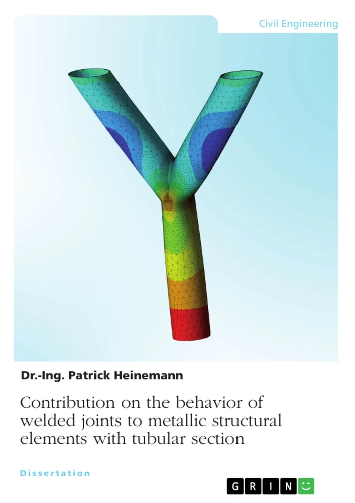
Table of Content
1 Table of Content
2 Table of Symbols and Variables
3 Introduction
3.1 Scope and Objectives of the Thesis
3.2 The Novelty of the Subject
3.3 Structure of the Thesis
4 State of the Art
4.1 Stress Distribution
4.2 Standards
4.3 FEA – Finite Element Analysis
5 Numerical Analysation – Preliminary Case Studies
5.1 Mesh Influence
5.1.1 CHS Joint
5.1.2 SHS Joint
5.2 Three-Dimensional Column
5.3 Two-Dimensional Column
5.3.1 SHS Joint
5.3.1.1 Symmetrical Model
5.3.1.2 Asymmetrical Model
5.3.2 CHS Joint
5.3.2.1 Symmetrical Model
5.3.2.2 Asymmetrical Model
5.4 Expanded Geometry – With Top Plate
5.4.1 Fixed Branch Length
5.4.1.1 Symmetrical Model
5.4.1.2 Asymmetrical Model
5.4.2 Variable Branch Length
5.4.2.1 Symmetrical Model
5.4.2.2 Asymmetrical Model
5.5 Expanded Geometry – Without Top Plate
5.5.1 Fixed Branch Length
5.5.1.1 CHS Joint
5.5.1.2 SHS Joint
5.5.2 Variable Branch Length
5.5.2.1 CHS Joint
5.5.2.2 SHS Joint
5.6 Influence of Member’s Length & Result Comparison
5.6.1 Results with top plate, fixed or expanded length
5.6.2 Results with top plate, variable and expanded length
5.6.3 Results without top plate, fixed length
5.6.4 Results without top plate, variable length
6 Numerical Analysation - Case Study Small-Scale Model (Testing Model)
6.1 CHS 2.0 mm Model
6.2 CHS 2.8 mm Model
6.3 SHS 2.8 mm Model
6.4 Result Comparison
7 Laboratory Test / Verification
7.1 Description
7.2 Testing Devices
7.2.1 Compression Machine
7.2.2 Strain Gauges
7.2.2.1 Technical Specification
7.2.2.2 Preparation & Conglutination
7.2.3 Resistance Transducer (“LVDT”)
7.2.4 Non-Destructive Tests
7.2.4.1 Image Processing
7.2.4.2 Liquid Testing
7.2.4.2 Ultrasonic Testing
7.3 Testing Specimen
7.3.1 Description of the Specimen
7.3.2 Flat Patterns
7.4 Testing Setup
7.5 Test Execution
7.6 Results
7.6.1 CHS Profile t = 2.0 mm
7.6.1.1 CHS 2.0 mm – 20° Inclination Angle
7.6.1.2 CHS 2.0 mm – 25° Inclination Angle
7.6.1.3 CHS 2.0 mm – 30° Inclination Angle
7.6.1.4 CHS 2.0 mm – 45° Inclination Angle
7.6.2 CHS Profile t = 2.8 mm
7.6.2.1 CHS 2.8 mm – 20° Inclination Angle
7.6.2.2 CHS 2.8 mm – 25° Inclination Angle
7.6.2.3 CHS 2.8 mm – 30° Inclination Angle
7.6.2.4 CHS 2.8 mm – 45° Inclination Angle
7.6.3 SHS Profile t = 2.8 mm
7.6.3.1 SHS 2.8 mm – 20° Inclination Angle
7.6.3.2 SHS 2.8 mm – 25° Inclination Angle
7.6.3.3 SHS 2.8 mm – 30° Inclination Angle
7.6.3.4 SHS 2.8 mm – 45° Inclination Angle
7.6.4 Comparison of the experimental Results
8 Summary and Comparison of the results
8.1 Comparison of the Strain Results
8.1.1 CHS 2.0 mm Profile
8.1.2 CHS 2.8 mm Profile
8.1.3 SHS 2.8 mm Profile
8.1.4 Overall Strain Comparison
8.2 Ultimate Resistance Y-joint
8.2.1 Elastic – Elastic
8.2.2 Plastic – Plastic
9 Discussion
9.1 Comparison to Literature
9.2 Comparison to Standard
9.3 Comparison to Preliminary Studies
10 Conclusion
11 Future Studies, Outlook and Publications
11.1 Future Studies and Outlook
11.2 Publications
12 Author’s Contribution
Research Objectives and Focus Themes
The primary aim of this dissertation is to characterize the mechanical behavior and ultimate resistance of a novel, full-overlapped Y-shaped steel joint, which is currently not sufficiently defined in existing structural standards. By investigating circular and squared hollow section profiles, the study seeks to understand how inclination angles, profile thickness, and geometry influence load-bearing capacity and stress distribution under axial compression, ultimately providing design charts for engineering practice.
- Numerical analysis of full-overlapped steel joints
- Experimental validation through laboratory testing series
- Evaluation of stress distribution and failure modes in nodes
- Development of design charts for elastic and plastic material states
- Influence assessment of inclination angles on joint resistance
Excerpt from the Book
3.1 Scope and objectives of the thesis
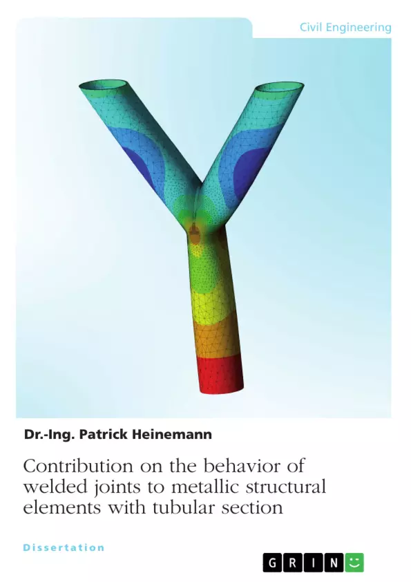
Steel structures, which are made of hollow section profiles are mainly used for industrial purposes (Heinemann, 2022d) or representative objects. They have got many advantages in opposite to H-beams, like the lightweight, carrying capacity, high rotational stiffness and many possible fields of applications (Heinemann, 2022a)(Heinemann, 2022b). Also, for special purposes, like offshore structures (Heinemann, 2021c)(Heinemann, 2022e), hollow section profiles are widely used due to the high resistance against three dimensional loads. For architectural reasons or geometrical requirements, vertical columns made out of steel hollow sections can have some ramifications. As an example, there are two or more members, which are connected to the vertical column with an inclination angle. These columns have got a visual shape of a tree (Heinemann, 2021a). It gives the structure a natural flair. Figure 3.1 shows an example of the “Skoda” automobile factory in Czech Republic (CZ) (Schlaich Bergermann Partner (SBP) 1995). The joint of the vertical member (in the following named as “chord”) and the connected members (in the following defined as “braces” or “branches”) is called node. This node is, due to the geometrical heterogeneity, the weakest part of the structure (Heinemann, 2022a)(Heinemann, 2022b)(Heinemann, 2022c).
There are mainly three options for creating this node. Firstly, there are steel sheets welded to the pipes. The connection for itself is made by bolts. Secondly, the complete node is made of cast steel and the straight pipes are connected to the cast steel (Fig. 3.1). This is the most expensive alternative, but there are nearly no imperfections. The production of the node can only be made in the factory after numerical designing. There is no possibility to create a cast steel node on the construction site. The third method is to weld the steel pipes in a three-dimensional way together. To avoid a horizontal steel plate, all pipes, in this case three members, have to be cut in a three-dimensional curved way.
Summary of Chapters
1 Table of Content: Lists the organizational structure of the thesis.
2 Table of Symbols and Variables: Provides definitions for all abbreviations and variables used throughout the work.
3 Introduction: Outlines the scope, the research novelty, and the overall objectives regarding full-overlapped tree-shaped joints.
4 State of the Art: Reviews existing literature, international standards, and finite element analysis methods for tubular steel joints.
5 Numerical Analysation – Preliminary Case Studies: Presents initial numerical investigations on mesh influences and simple joint geometries as a basis for final models.
6 Numerical Analysation - Case Study Small-Scale Model (Testing Model): Detailed numerical modeling of the specimens specifically analyzed for validation against laboratory test results.
7 Laboratory Test / Verification: Describes the experimental setup, testing procedures, and measured results for the verification of the numerical simulations.
8 Summary and Comparison of the results: Compares numerical and experimental strain results and introduces design charts for ultimate resistance calculation.
9 Discussion: Evaluates the collected results in the context of academic literature, standards, and previous studies.
10 Conclusion: Summarizes the key findings regarding the mechanical resistance and failure behavior of the researched Y-joint types.
11 Future Studies, Outlook and Publications: Suggests potential research pathways and lists the author’s relevant publications.
12 Author’s Contribution: details the specific contributions provided by the author to the field of standard-undefined steel joint design.
Keywords
Steel structures, hollow section profiles, Y-shaped joint, full-overlapped, finite element analysis, numerical modeling, laboratory testing, inclination angle, ultimate resistance, weld joint, strain distribution, elastic-plastic behavior, structural stability, tree-shaped columns, Eurocode 3
Frequently Asked Questions
What is the core subject of this thesis?
The thesis explores the structural behavior and load-bearing capacity of full-overlapped, Y-shaped steel joints using hollow section profiles, which are not currently addressed by standard design codes.
What are the central thematic fields?
The work covers structural engineering, numerical modeling using Finite Element Analysis (FEA), experimental laboratory verification, and the derivation of design criteria for atypical welded steel connections.
What is the primary research goal?
The objective is to calculate the ultimate resistance of these specific joints and provide design charts and correlation factors for engineers to apply in practical construction.
Which scientific methods are applied?
The author utilizes a combined approach consisting of numerical simulation via ANSYS software and extensive experimental verification through physical load testing and strain measurement on customized specimens.
What topics are covered in the main body?
The main body moves from preliminary numerical case studies to a detailed small-scale testing model, followed by a comprehensive verification against laboratory results and final comparison with existing standardization frameworks.
Which keywords best characterize the work?
Key terms include: Steel joints, Hollow section, Full-overlapped Y-joint, Finite Element Analysis, Structural resistance, Inclination angle, and Experimental verification.
Why are these specific Y-joint designs considered unconventional?
They involve a full overlap of three members without traditional intermediate plates, leading to complex geometric and stress scenarios that current standard codes like Eurocode 3 do not officially provide formulas for.
What significance do the generated design charts have?
They provide the first analytical reference for practicing engineers to estimate the resistance of these specific tree-shaped column nodes, bridging a critical gap in current structural standards.
How does the author evaluate the quality of the FEA results?
The author performs mesh metric evaluations, examining factors like element skewness and aspect ratios, and validates the numerical output by comparing it directly with measured strain data from physical laboratory load tests.
Ende der Leseprobe aus 183 Seiten
- nach oben
- Arbeit zitieren
- Dr.-Ing. Patrick Heinemann (Autor:in), 2022, Contribution on the behavior of welded joints to metallic structural elements with tubular section, München, Page::Imprint:: GRINVerlagOHG, https://www.diplomarbeiten24.de/document/1323678

neugierig - aktuell - relevant
Entdecken Sie hilfreiche Tipps und Tricks rund ums Studium!

Entdecken Sie hilfreiche Tipps und Tricks rund ums Studium!
Ihre Hausarbeit / Abschlussarbeit:

- - Publikation als E-Book und Buch
- - Hohes Honorar auf die Verkäufe
- - Für Sie komplett kostenlos - mit ISBN
- - Es dauert nur 5 Minuten
- - Jede Arbeit findet Leser

- © GRIN Publishing GmbH.
- Alle Inhalte urheberrechtlich geschützt. Kopieren und verbreiten untersagt.
- info@grin.com
- AGB
- Open Publishing
Der GRIN Verlag hat sich seit 1998 auf die Veröffentlichung akademischer eBooks und Bücher spezialisiert. Der GRIN Verlag steht damit als erstes Unternehmen für User Generated Quality Content. Die Verlagsseiten GRIN.com, Hausarbeiten.de und Diplomarbeiten24 bieten für Hochschullehrer, Absolventen und Studenten die ideale Plattform, wissenschaftliche Texte wie Hausarbeiten, Referate, Bachelorarbeiten, Masterarbeiten, Diplomarbeiten, Dissertationen und wissenschaftliche Aufsätze einem breiten Publikum zu präsentieren.
Kostenfreie Veröffentlichung: Hausarbeit, Bachelorarbeit, Diplomarbeit, Dissertation, Masterarbeit, Interpretation oder Referat jetzt veröffentlichen!
Folgen Sie GRIN auf


- GRIN Verlag GmbH
-
- Nymphenburger Str. 86
- 80636
- Munich, Deutschland
- +49 89-550559-0
- +49 89-550559-10
- info@grin.com
-